
Practical Clamping Force:
In practice this high clamping force is only ever realised when it is not needed(!), that is when bending thin steel workpieces. When bending non-ferrous workpieces the force will be less as shown in the graph above, and (a little curiously), it is also less when bending thick steel workpieces. This is because the clamping force needed to make a sharp bend is very much higher than that needed for a radius bend. So what happens is that as the bend proceeds the front edge of the clampbar lifts slightly thus allowing the workpiece to form a radius.
The small air-gap which is formed causes a slight loss of clamping force but the force needed to form the radius bend has dropped more sharply than has the magnet clamping force. Thus a stable situation results and the clampbar does not let go.
What is described above is the mode of bending when the machine is near its thickness limit. If an even thicker workpiece is tried then of course the clampbar will lift off.
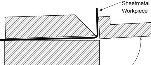
This diagram suggests that if the nose edge of the clampbar was radiused a little, rather than sharp, then the air gap for thick bending would be reduced.
Indeed this is the case and a properly made Magnabend will have a clampbar with a radiused edge. (A radiused edge is also much less prone to accidental damage compared with a sharp edge).
Marginal Mode of Bend Failure:
If a bend is attempted on a very thick workpiece then the machine will fail to bend it because the clampbar will simply lift off. (Fortunately this does not happen in a dramatic way; the clampbar just lets go quietly).
However if the bending load is only slightly greater than the bending capacity of the magnet then generally what happens is that the bend will proceed to say about 60 degrees and then the clampbar will start to slide backwards. In this mode of failure the magnet can only resist the bending load indirectly by creating friction between the workpiece and the bed of the magnet.
The thickness difference between a failure due to lift-off and a failure due to sliding is generally not very much.
Lift-off failure is due to the workpiece levering the front edge of the clampbar upwards. The clamping force at the front edge of the clampbar is mainly what resists this. Clamping at the rear edge has little effect because it is close to where the clampbar is being pivoted. In fact it is only half of the total clamping force which resists lift-off.
On the other hand sliding is resisted by the total clamping force but only via friction so the actual resistance depends on the coefficient of friction between the workpiece and the surface of the magnet.
For clean and dry steel the friction coefficient can be as high as 0.8 but if lubrication is present then it could be as low as 0.2. Typically it will be somewhere in between such that the marginal mode of bend failure is usually due to sliding, but attempts to increase friction on the surface of the magnet have been found to be not worthwhile.
Thickness Capacity:
For an E-type magnet body 98mm wide and 48mm deep and with a 3,800 ampere-turn coil, the full length bending capacity is 1.6mm. This thickness applies to both steel sheet and aluminium sheet. There will be less clamping on the aluminium sheet but it requires less torque to bend it so this compensates in such a way as to give similar gauge capacity for both types of metal.
(To achieve the maximun bending capacity the extension piece needs to be fitted to the bending beam).
There needs to be some caveats on the stated bending capacity: The main one being that the yield strength of the sheet metal can vary widely. The 1.6mm capacity applies to steel with a yield stress of up to 250 MPa and to aluminium with a yield stress up to 140 MPa.
The thickness capacity in stainless steel is about 1.0mm. This capacity is significantly less than for most other metals because stainless steel is usually non-magnetic and yet has a reasonably high yield stress.
Another factor is the temperature of the magnet. If the magnet has been allowed to become hot then the resistance of the coil will be higher and this in turn will cause it to draw less current with consequent lower ampere-turns and lower clamping force. (This effect is usually quite moderate and is unlikely to cause the machine to not meet its specifications).
Finally, thicker capacity Magnabends could be made if the magnet cross section was made larger.
Post time: Dec-16-2020