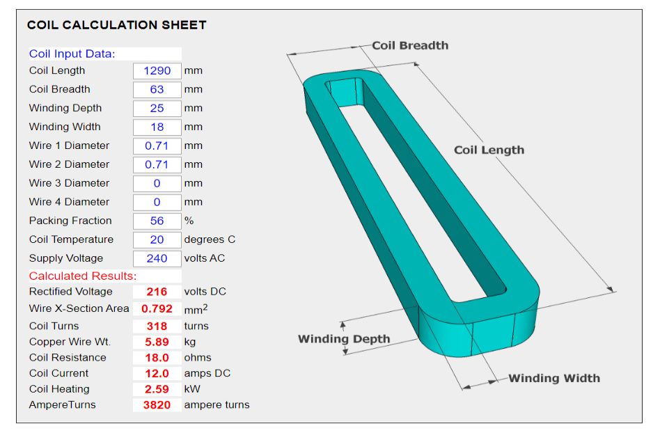
People often ask me to check their calculations for “Magnabend” coil designs . This prompted me to come up with this web page which enables automatic calculations to be performed once some basic coil data has been entered.
Many thanks to my colleague, Tony Grainger, for the JavaScript program which performs the calculations on this page.
COIL CALCULATOR PROGRAM
The calculation sheet below was designed for “Magnabend” coils but it will work for any magnet coil which operates from rectified (DC) voltage.
To use the calculation sheet simply click in the Coil Input Data fields and type in your coil dimensions and wire sizes..
The program updates the Calculated Results section every time you hit ENTER or click in another input field.
This makes it very quick and easy to check a coil design or to experiment with a new coil design.
The pre-filled numbers in the input data fields are just an example and are typical numbers for a 1250E Magnabend folder.
Replace the example numbers with your own coil data. The example numbers will return to the sheet if you refresh the page.
(If you wish to preserve your own data then Save or Print the page before refreshing it).
Suggested Coil Design Procedure:
Input the dimensions for your proposed coil, and your intended supply voltage. (Eg 110, 220, 240, 380, 415 Volts AC)
Set Wire 2, 3 and 4 to zero and then guess a value for the diameter of Wire1 and note how many AmpereTurns result.
Adjust Wire1 diameter until your target AmpereTurns are achieved, say about 3,500 to 4,000 AmpereTurns.
Alternatively you can set Wire1 to a preferred size and then adjust Wire2 to achieve your target, or set both Wire1 and Wire2 to preferred sizes and then adjust Wire3 to achieve your target etc.
Now look at the Coil Heating (the power dissipation)*. If it is too high (say more than 2 kW per metre of coil length) then AmpereTurns will need to be reduced. Aternatively more turns can be added to the coil to reduce the current. The program will automatically add more turns if you increase the width or depth of the coil, or if you increase the Packing Fraction.
Lastly consult a table of standard wire gauges and choose a wire, or wires, that have a combined cross-sectional area equal to the value calculated in step 3.
* Note that power dissipation is very sensitve to AmpereTurns. It is a square law effect. For instance if you doubled AmpereTurns (without increasing the winding space) then power dissipation would increase by 4 times!
More AmpereTurns dictate thicker wire (or wires), and thicker wire means more current and higher power dissipation unless the number of turns can be increased to compensate. And more turns means a larger coil and/or a better Packing Fraction.
This Coil Calculation Program allows you to easily experiment with all those factors.
NOTES:
(1) Wire sizes
The program provides for up to 4 wires in the coil. If you enter a diameter for more than one wire then the program will assume that all the wires will be wound together as if they were a single wire and that they are joined together at the start and at the end of the winding. (That is the wires are electrically in parallel).
(For 2 wires this is called bifilar winding, or for 3 wires trifilar winding).
(2) The Packing Fraction, sometimes called the fill factor, expresses the percentage of the winding space that is occupied by the copper wire. It is affected by the shape of the wire (usually round), the thickness of insulation on the wire, the thickness of the coil outer insulation layer (typically electrical paper), and the method of winding. The winding method can include jumble winding (also called wild winding) and layer winding.
(3) The Coil Power resulting from the pre-filled example numbers (see above) is 2.6 kW. This figure may seem rather high but a Magnabend machine is rated for a duty cycle of only about 25%. Thus in many respects it is more realistic to think of the average power dissipation which, depending on how the machine is being used, will be only a quarter of that figure, typically even less.
If you are desiging from scratch then the overall power dissipation is a very import parameter to consider; if it is too high then the coil will overheat and could be damaged.
Magnabend machines were designed with a power dissipation of around 2kW per metre of length. With a 25% duty cycle this translates to around 500W per metre of length.
Just how hot a magnet will get depends on many factors in addition to the duty cycle. Firstly the thermal inertia of the magnet, and whatever it is in contact with, (for instance the stand) means that self-heating will be relatively slow. Over a longer period the magnet temperature will be influenced by the ambient temperature, the surface area of the magnet and even by what colour it is painted! (For instance a black colour radiates heat better than a silver colour).
(4) Note that the program allows you to enter a temperature for the coil and thus you can see its effect on the coil resistance and the coil current. Because hot wire has a higher resistance then it results in a reduced coil current and consequently also reduced magnetising force (AmpereTurns). The effect is quite significant.
(5) The program assumes that the coil is wound with copper wire, which is the most practical type of wire for a magnet coil.
Aluminium wire is also a possibility, but aluminium has a higher resistivity than copper (2.65 ohm metre compared to 1.72 for copper) which leads to a less efficient design. If you need calculations for aluminium wire then please contact me.
(6) If you are designing a coil for a “Magnabend” sheet metal folder, and if the magnet body is of reasonably standard cross section size (say 100 x 50mm) then you should probably aim for a magnetising force (AmpereTurns) of around 3,500 to 4,000 ampere turns. This figure is independent of the actual length of the machine. Longer machines will need to use thicker wire (or more strands of wire) to achieve that same value for AmpereTurns.
However, for a given overall size of magnet and thickness of poles, more ampere turns can only be gained at the expense of higher current and thus higher power dissipation and consequent increased heating in the magnet. That may be OK if a lower duty cycle is acceptable otherwise a larger winding space is needed to accommodate more turns, and that means a larger magnet (or thinner poles).
(7) If you are designing, say, a magnetic chuck then a much higher duty cycle will be needed. (Depending on the application then perhaps a 100% duty cycle might be needed). In that case you would use thinner wire and perhaps design for a magnetising force of say 1,000 ampere turns.
The above notes are just to give an idea of what can be done with this very versatile coil calculator program.
Standard Wire Gauges:
Historically wire sizes were measured in one of two systems:
Standard Wire Gauge (SWG) or American Wire Gauge (AWG)
Unfortunately the gauge numbers for these two standards don’t quite line up with each other and this has led to confusion.
Nowadays it is best to ignore those old standards and just refer to the wire by its diameter in millimetres.
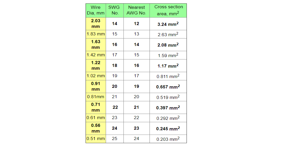
Here is a table of sizes that will encompas any wire that is likely to be needed for a magnet coil.
The wire sizes in bold type are the most commonly stocked sizes so preferrably choose one of those.
For instance Badger Wire, NSW, Australia stock the following sizes in annealed copper wire:
0.56, 0.71, 0.91, 1.22, 1.63, 2.03, 2.6, 3.2 mm .
Please contact me with any questions or comments.
Post time: Sep-15-2020


