
HOW TO MAKE THE SLOTTED CLAMPBAR
“The following page is used with permission from:
http://aaybee.com.au/Magnabend/Magnabend_Homepage.html ” Thank you to Alan Stuart Bottomley (the magnabend’s inventor) Permission to Use Magnabend Website Material.
The Slotted Clampbar
(Click on the drawing for a larger image)
The slotted clampbar is one of several innovations that were developed for the Magnabend sheetmetal folding machine.
It provides for the bending of shallow boxes and trays without the need for adjustable “fingers”.
The sections between the slots of the this clampbar are the equivalent of the adjustable fingers of a conventional pan-brake machine, but with the Magnabend clampbar they never need to be adjusted because the design provides for all sizes!
This innovation resulted from the following observations:
Firstly it was noticed that it is not necessary to have a continuous bending edge because bends will carry across reasonable gaps left between the fingers with no noticeable effect on the bend provided that the fingers are well aligned, and they always are well aligned on the slotted clampbar because it has fixed “fingers”.
Secondly it was realised that by careful arrangement of the slots it is possible to provide for an infintely graded set of sizes up to almost the full length of the clampbar.
Thirdly it was noted that finding the optimum positions for the slots was NOT a trivial problem.
Although it is trivial if a large number of slots are provided.
But the interesting problem is to find the minimum number of slots which will provide for all sizes.
There seemed to be no analytic solution to this problem. That fact turned out to be of some intererst to 2 mathematicians at the University of Tasmania.
However the problem was solved by engineers at Magnetic Engineering (mainly Mr Geoff Fenton) who came up with a computer program that used the “Monte Carlo Method” to find the best set of slot positions. This program used a random number generator to provide a guess for a set of positions which would then be tested against a previous best guess for a set of positions. Thus millions of possibilities could be tested.
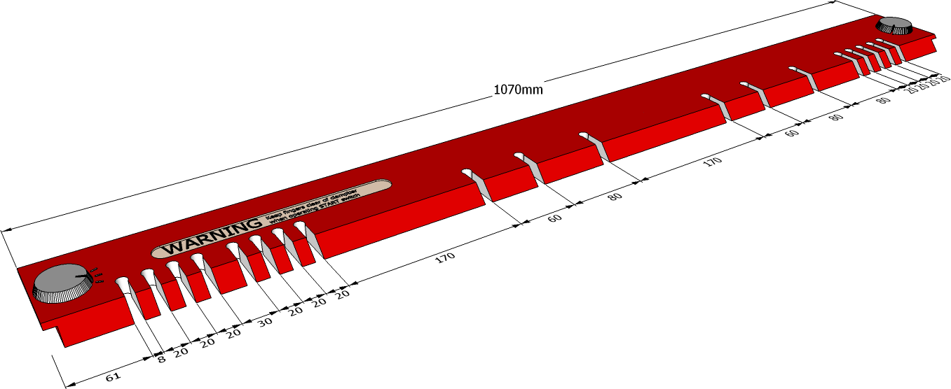
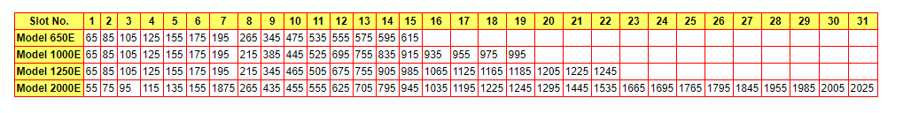
Optimised Slot Positions for 4 Magnabend Models:
- The positions shown in the table below are measured from the left end of the clampbar and are to the centre of the slots.
Each slot is 8mm wide. - Model designations express the nominal bending length of the model. Actual overall lengths of each model are as follows:
MODEL 650E: 670mm, MODEL 1000E: 1050mm, MODEL 1250E: 1300mm, MODEL 2000E: 2090mm.
The overall length of the clampbars including the finger grips at each end: add 20mm to the above lengths. - The dimension for the depth of the slots is not shown on the above drawing. This is somewhat optional but a depth of 40 to 50 mm is suggested.
FORMING TRAYS USING THE SLOTTED CLAMPBAR
The Slotted Clampbar, when supplied, is ideal for making shallow trays and pans quickly and accurately.
The advantages of the slotted clampbar over the set of short clampbars for making trays are that the bending edge is automatically aligned to the rest of the machine, and the clampbar automatically lifts to facilitate the insertion or removal of the workpiece. Never-the-less, the short clampbars can be used to form trays of unlimited depth, and of course, are better for making complex shapes.
In use, the slots are equivalent to gaps left between the fingers of a conventional box & pan folding machine. The width of the slots is such that any two slots will fit trays over a size range of 10 mm, and the number and locations of the slots are such that for all sizes of tray, there can always be found two slots that will fit it.
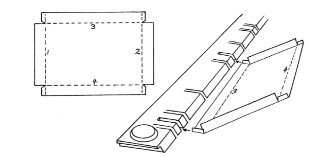
To fold up a shallow tray:
- Fold-up the first two opposite sides and the corner tabs using the slotted clampbar but ignoring the presence of the slots. These slots will not have any discernible effect on the finished folds.
- Now select two slots between which to fold-up the remaining two sides. This is actually very easy and surprisingly quick. Just line-up the left side of the partly made tray with the leftmost slot and see if there is a slot for the right side to push into; if not, slide the tray along till the left side is at the next slot and try again. Typically, it takes about 4 such tries to find two suitable slots.
- Finally, with the edge of the tray under the clampbar and between the two chosen slots, fold up the remaining sides. The previously formed sides go into the selected slots as the final folds are completed.
With tray lengths that are nearly as long as the clampbar it may be necessary to use one end of the clampbar in lieu of a slot.
Post time: Jun-19-2019